Image Credit: Rick Miller
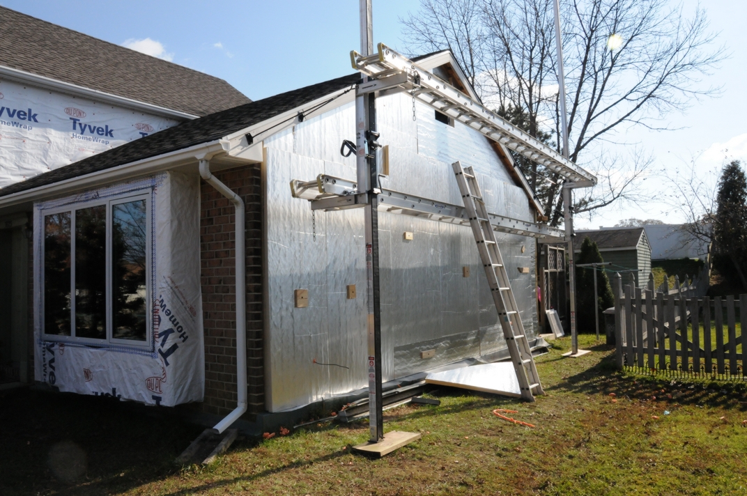
Image Credit: Rick Miller The roof has been extended and new asphalt shingles have been woven into the existing shingles. Installation of the two layers of polyiso has begun, from the top working downward. The ledgers that support the new roof over the second-floor windows were installed over the uninsulated attic space, so the area does not need to be insulated. Later, the upper part of the chimney was removed and the hole in the roof was patched.
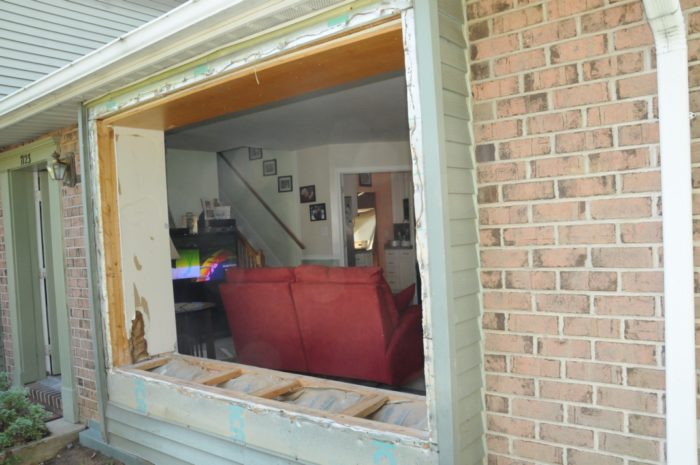
Image Credit: Rick Miller Additional south-facing windows were installed in the family room. This room would later get an interior makeover, but during the construction phase it was used as a warehouse for windows, polyiso, and just about anything else that needed to be stored. The visible layer of 1-inch-thick pink XPS was used as the first layer of exterior rigid foam in the area where an east-facing window was removed. The fireplace insert was also later removed.
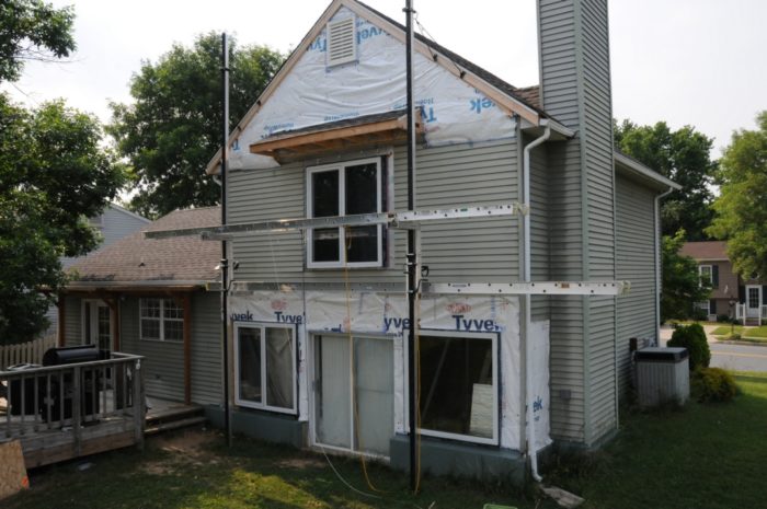
Image Credit: Rick Miller Most of the new solar glazing has been installed. The new windows were installed on extended window bucks so that they would later be flush with the added layers of new rigid foam insulation. The old siding was left in place as long as was possible, and housewrap was tacked up temporarily, to help protect against the weather during construction.
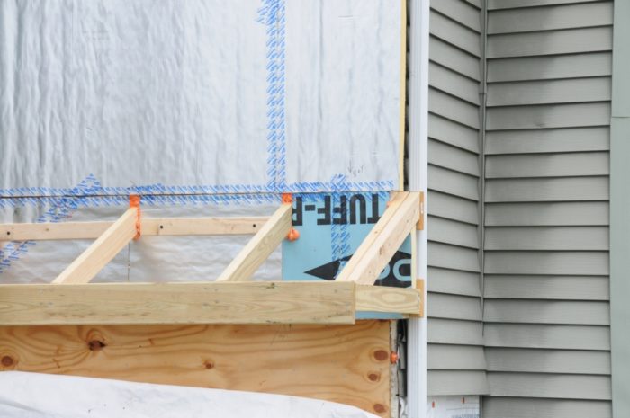
Image Credit: Rick Miller The horizontal ledgers installed to support the roofs over the first-floor windows were buried in rigid foam to help reduce the thermal bridging of the overhang framing.
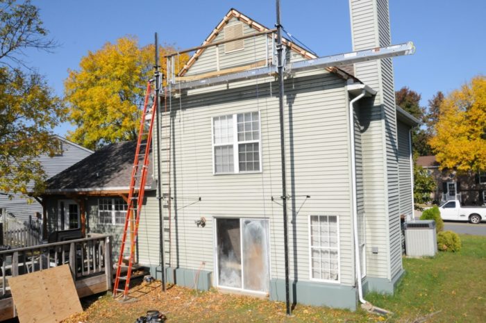
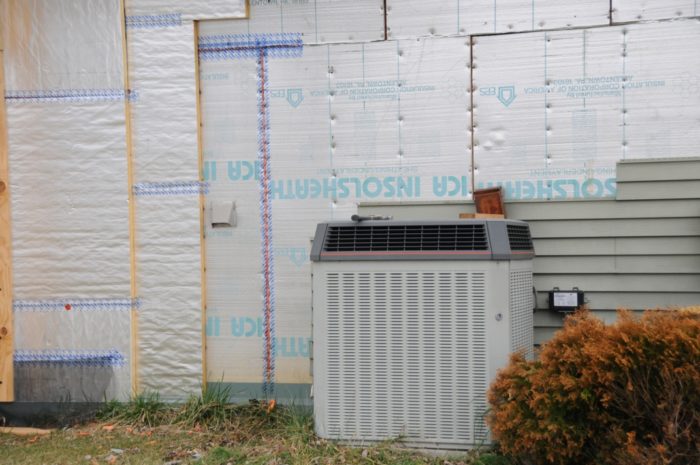
Image Credit: Rick Miller The gaps that had opened up between the original sheets of EPS were filled with spray foam and then taped. Once these gaps were sealed, two new layers of rigid foam were installed. The old heat pump unit was failing, but it wouldn’t need to operate too much longer.
Image Credit: Rick Miller The large window in the living room needs extended window bucks, but I’m running out of time. The TV shows the projected path of a hurricane coming that night.
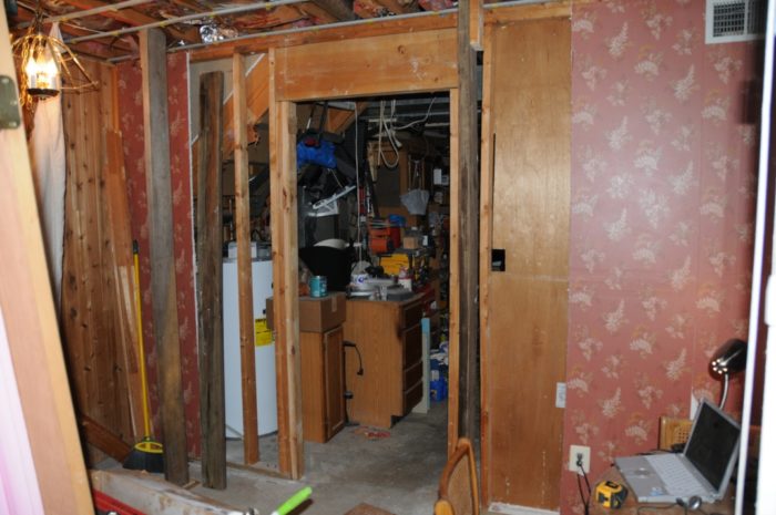
Image Credit: Rick Miller The electric-resistance water heater under the stairs in the utility room was eventually replaced by a wine rack, a pantry, and an extension of the family room. The temporary posts supporting the ceiling joists will allow the door header to be replaced by a longer header to support a brick arch.
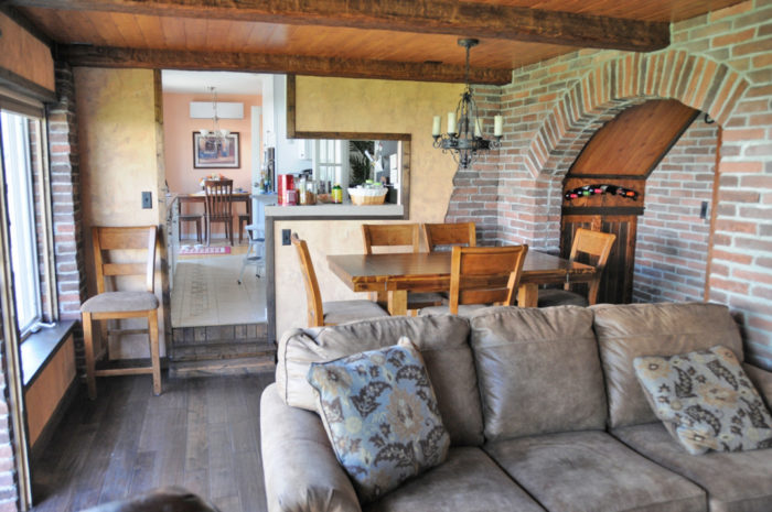
Image Credit: Rick Miller The family room now looks a little Old World. The indoor unit of the Fujitsu 12 RLS2 ductless minisplit system is visible at the far end of the kitchen.
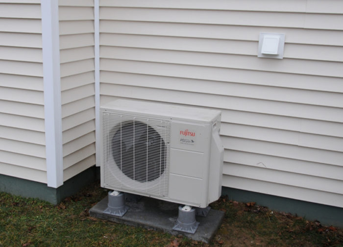
Image Credit: Rick Miller The outdoor unit of the Fujitsu 9 RLS2 ductless minisplit system. The former chimney chase worked great for routing the refrigerant lines upstairs.
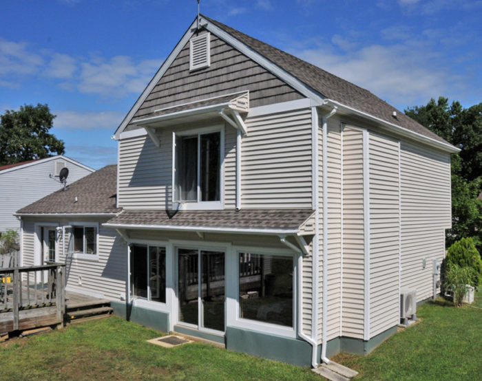
Image Credit: Rick Miller The finished south elevation — the solar “business end” of the house.
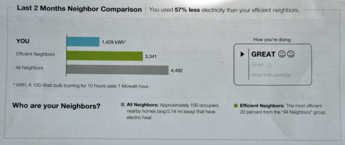
Image Credit: Rick Miller Every two months, the house receives this “award”: a Two-Smiley-Face letter from the local electric utility.
Image Credit: Rick Miller
How to get a Two-Smiley-Face letter from your electric utility
In 1983, the Heron was one of five cookie-cutter models offered in Bay Country, a tract housing development in a suburb of Baltimore, Maryland. Perhaps a little ahead of its time, the design featured walls with 1-inch-thick expanded polystyrene (EPS) insulation over the standard 2×4 walls filled with fiberglass batts.
Many years later, the original green aluminum siding was faded, and the cold leaky windows whispered that it was time for a new approach to “green” — or at least an energy-efficiency makeover. When an old house needs new windows and siding, it is a great time to add exterior insulation and to tighten it up against air infiltration. That was the basic approach we took to reduce our all-electric home’s energy bill.
It seemed to me that the house was destined to mature into a new phase, more modern and energy-efficient: able to take advantage of the amazing, timeless, natural power of passive solar energy.
The floor plan is small, although it was enough for a family of four for many years. The exterior lines are fairly simple, so that the wall area exposed to the weather is not large compared to the volume enclosed. The long side of the house faces 20 degrees east of solar south, and there are no windows on the west wall, keeping unwanted heat gain from the late afternoon summer sun to a minimum.
The fairly open floor plan was ideal for the use of highly efficient ductless minisplits to replace the aging central heat pump system and its bulky air handler and dusty ducts.
Two smiley faces are better than one
Since we completed our energy retrofit work, our house hasn’t received any awards. (It may qualify for some sort of award if I ever become interested in such things.) Instead of receiving awards, the house has provided many rewards: comfort, quiet, very low electric bills, and general satisfaction.
The closest thing to an energy-efficiency award the house has received is a letter from the local electric utility titled “Home Energy Report.” The report compares the electricity use for the previous two months with that of the closest 100 occupied houses. In the section called “How you’re doing,” we were informed that our house is doing “great.” This was followed by not one, but two smiley faces.
Do awards really get any better than that? The colder it gets, the better our house performs compared to neighboring houses. According to the Two-Smiley-Face Letter, in January and February of this year, the house used 57% less electricity than the most efficient neighboring houses.
The sun was my inspiration
The earth and every house on it are powered by the sun or other stars, mostly with energy sources that are really just solar energy converted into some other form. Oil, natural gas, and coal are natural storage batteries of solar energy absorbed by the earth long before our time. Wood and cow pies are other examples of solar energy storage batteries that some people use to heat their homes.
Solar energy also drives wind and hydro power. We currently harness nuclear energy split from radioactive elements heavier than iron, believed to have been made mostly by supernovae — explosions of stars. Our electricity is converted inefficiently from one of these solar storage batteries. The batteries are not particularly easy to recharge, so that it seems best to use solar energy directly from the source.
One cold and sunny winter day, before I started the energy retrofit, I was lying on the rug in front of the south-facing sliding glass door with my dog. With the sun pouring in, I had never felt so naturally cozy. The old door may have been leaky but the glazing was clear, and it was collecting a lot of heat.
While I was lying there, I decided that at some time in the future it would be possible for people to live very comfortably in homes completely powered directly by solar energy (using passive solar energy, photovoltaics, or some other direct form), coupled with advanced storage techniques to carry the house through the night and cloudy weather. I also then decided I would retrofit this house to maximize energy efficiency, using the classic, purist approach:
- First, reduce the energy footprint as much as possible; all techniques to conserve energy, big and small, add up.
- Second, use the sun as much and as directly as possible.
This was a DIY project
Almost every part of the house was reworked, and I did all the design and trade work myself, except for the installation of the minisplit heat pumps. Energy modeling was initially done with Energy Plus, but since it was so cumbersome to use, I was happy to see the introduction of the easier-to-use BEopt software.
Before I started, I knew it would be a huge amount of work, particularly since I had very little experience with any of the trades or design. Now we’re almost finished and we’ve been very happy with the results, with big improvements in energy efficiency and aesthetics.
Fiberglass batts were added in the attic
The house has two separate conventionally ventilated attics with access hatches. As built, both attics had about 12 inches (R-30) of blown-in fiberglass insulation. No attempt had been made to seal air leaks at the hatches.
The attic was the first part of the house to receive an insulation upgrade. I used canned spray foam to seal every ceiling penetration I could find. The hatches were covered with several layers of rigid foam board, and I installed foam weatherstripping tape at the perimeter of the hatches.
As part of the retrofit, three layers of R-19 fiberglass batt insulation were rolled out over the existing loose fiberglass, with each layer perpendicular to the one below. Nominally, this adds up to a total of R-87. Of course, the attics are not really R-87, since the three layers do not fit all the way to the edges near the soffits, and because of the inevitable gaps between rows of rolled fiberglass.
The estimated actual overall attic insulation level used in our energy simulations is R-70.
Adding exterior polyiso to the walls
The original walls consist of 2x4s, 16 inches on center, with R-13 fiberglass batts between the studs and 1-inch-thick EPS tacked to the exterior of the studs, for a nominal R-value of 17. Considering the thermal bridging of the closely spaced studs, the actual R-value of the original walls was about R-14.
Since new siding was needed, the old aluminum siding was stripped away, revealing the aging EPS. By now, many builders know that EPS panels can shrink over time. I discovered gaps between almost all the edges of the EPS foam boards, some as wide as 1 inch. Most of this original foam board was left in place, refastened to the studs as needed. I sealed all of the gaps with spray foam before taping the seams with construction tape.
The original fiberglass batts were mostly left in place, with any obvious, accessible problems corrected. It was easy to see that the house had been overly and randomly ventilated in places, but at least the air had been filtered (joke), as evidenced by some dirty fiberglass appearing every so often as the siding came off.
After those relatively minor repairs, the insulation value of the walls was increased, basically following the REMOTE “outsulation” method that originated in Alaska. I installed two layers of 2-inch-thick polyisocyanurate foam board on the exterior side of the existing EPS. All of the polyiso seams were staggered and the seams were sealed with canned spray foam and construction tape.
The taped polyiso is the air barrier for the walls of this house. The polyiso is also the water-resistant barrier (WRB) to which the flashing for the windows is sealed. I attached the two additional layers of polyiso, along with the furring strips, to the studs using 7½-inch Fastenmaster construction screws. It is not as difficult as it sounds to run the screws through all that material thickness and hit the studs.
The original plan included leaving a gap between the furring strips so that the back side of the siding would be ventilated. We decided to install vinyl siding, however, and vinyl siding manufacturers want absolutely no liability for a wavy finish on the siding. They want nothing but a perfectly flat (planar) substrate for siding installation, and most manufacturers state that requirement in their installation instructions. Rather than risk wavy siding or a fight with the manufacturers, I filled in almost all of the gaps between the furring strips with ¾-inch extruded polystyrene (XPS) rigid foam before I installed the new vinyl siding.
According to our original calculations, the total R-value of these modified walls would be about R-40: R-14 for the fiberglass batts and EPS plus R-26 for the 4 inches of polyiso (assuming that polyiso is rated at R-6.5 per inch).
At first, I wasn’t familiar with the R-value testing protocol that specifies that insulation products be tested at a mean temperature of 75°F. This seems like a useless temperature to assess cold-weather performance. In cold weather, polyiso performs poorly — more like R-5 per inch rather than R-6.5 per inch. Therefore, the modified walls of this house are approximately at R-34 — or maybe R-35, because the inner layer of polyiso probably stays a little warmer in the winter since it is insulated by the outer layer.
Installing more south-facing glazing
Windows are amazing. We all like natural light. We all want it to look and feel like we are outside in beautiful weather, even when we are inside. Windows help do that, but with our current state of technology, they provide very little insulation; they are like holes in the thermal envelopes of our houses.
For the energy-conscious person, windows are one of those things you think of when you say, “You can’t live with them and you can’t live without them.” We all like windows because they feel good; they connect us to our natural environment. That natural feeling is dramatically enhanced when windows are used for intelligent energy collection from the sun, our natural energy source.
The original windows of our house were double-hung windows with aluminum frames and clear double glazing (air filled).
The south-facing area of this glazing was 7% of the total floor area, so the house was “sun-tempered,” according to the language of passive solar design. Sun-tempered means that a non-trivial amount of the winter heating demand of the house was being supplied by the sun.
Seven percent solar glazing is an important quantity in passive solar design: it is considered the largest percentage of south-facing glazing that should be used without adding extra thermal mass to the interior of the house. All houses include some internal thermal mass — for example, drywall and furniture — and that thermal mass is enough to temper the heat introduced by south-facing glazing up to the 7% value, in a way that avoids overheating.
The original windows’ contribution to the home’s winter heating demand was noticeable. It could be felt by someone familiar with the concept. No attempt was made to quantify, either by calculation or modeling, the heating contribution made by the original south-facing windows.
The plan to maximize the passive solar energy contribution to help meet the heating load basically involved adding as much glazing to the south side as seemed both possible and reasonable. After adding more south-facing windows, we now have solar glazing amounting to 9.3% of the total floor area of the house. New, deeper window bucks were installed to accommodate more and larger windows on the south side, and to bring all of the new windows out flush with the 4 inches of new foam board on the walls.
We love our passive solar house
These days, people’s opinions on the use of passive solar energy range from love, to hate, to anywhere in between. We love it.
We love the brilliant winter sun that seems to blind some other people. We don’t care about color fading. We have no problem opening and closing thermal curtains, on a daily basis, if needed.
We have never felt what we would characterize as “overheating” due to passive solar gain in this house. The passive solar features sometimes provide a little more heat than wanted during parts of the shoulder seasons in this climate. On those very few days, opening the windows is easy, and we welcome the cool fresh air.
Solar fraction calculations
Calculations and computer modeling indicate that the new windows provided about 54% of the heating demand for the house during the winter of 2013-2014 (the coldest winter in this area in the past five years). The minisplit units were installed in February 2013. Thanks to the south-facing glazing, the downstairs unit has spent a lot of time sampling the air and looking for something to do during the heating seasons.
Most of the calculations needed to determine the solar fraction, or percentage of the heating load supplied by the sun, are easily performed by readily available computer simulations, such as BEopt and others. For various reasons, these calculations are not scientifically precise, but they provide a useful estimation of heat loss and gain. The calculations I used to determine the solar fraction were as follows:
- The heat loss formula for determining transmission losses through floors, roofs, and walls is Q = A • U • ΔT. In other words, the rate of heat flow through a building assembly (in Btu/h) is equal to the area of the assembly (in ft²) times the U-factor (in Btu/ft² • h • F°) of the assembly times the ΔT (in F°).
- For our house, I calculated that the total heat loss of the house is about 190.7 Btu/h x delta-T in F°. I calculated that number using the known insulating ability (R-value or its reciprocal, U-factor) of walls, ceilings, floor and windows, the geometric areas of those features, and the infiltration rate of outside air (either estimated or measured).
- With the rate of heat loss known, heating degree days (HDD) can be used to determine the amount of heat loss over a period of time. HDDs do not have to be calculated; it is a statistic monitored by weather services and is based on historical temperature data. The HDD is a number that represents how much (in F°) and for how long (in days) the outside temperature was below a base temperature during that time when the house needs heating. The base temperature usually used in the U.S. is 65°F. Some simple examples of how HDDs are determined are as follows: If the outside temperature is 10 F° below 65°F for one day, then that is 10 HDDs. If the temperature is 5 F° below 65°F for two days, that is also 10 HDD. Of course, the outside temperature varies over the course of any winter day. It is not just simply and constantly five or ten degrees, for example, below 65°F. So, the average of the hourly temperature values (the ones below 65°F) that occur throughout the day can be used for HDD determination. The units for HDD are F° x day.
- Now the total amount of heat needed to keep the house warm over the winter season can be calculated. The amount of heat needed is 4,577 Btu / (day x F°) x HDD. There were about 5,019 HDDs for this area during the winter of 2013-2014. So, the entire heat loss of the house for that particular winter season was: 4,577 Btu / (F° x day) x 5,019 (F° x day) = 22,971,963 Btu.
- The idea is to keep the house at 65°F during the heating season, so it is necessary to supply enough space heat to balance the heat loss. The heating load is typically considered to be only the amount of heat required to achieve 65°F because the heat to raise the other 5°-7°F degrees needed to reach the 70°-72°F “standard” comfortable indoor temperature is considered to be provided by such things as household appliances, lighting, and bodies.
- So, the heat load for the 2013-2014 heating season was about 22.972 million Btu. How much of that heat was provided by the solar glazing on the south side of the house? To determine the contribution by the solar glazing, the primary information needed is the area of the glazing, the solar direction it faces, the solar heat gain coefficient (SHGC, a standard window specification), and the average amount of sunshine (insolation) for the area during the months of the heating season. Historical insolation by month and geographic area are readily available from the National Renewable Energy Laboratory (NREL) website. Window heat gain calculations that provide fairly good results are not difficult, but there are many steps and iterations, so computer programs really shine at the task. One online calculator I have recently discovered that appears to deliver reasonable results, when reasonable information is entered, is offered by the Sustainable by Design website. The author of the calculator “estimates (rather subjectively) that the overall calculation is accurate to within about 20% as an average value.” After using this calculator, I believe it is far more accurate for my situation than 20%, because its results are similar to those I originally got a few years ago, using the more sophisticated Energy Plus computer program. The online calculator determines, for this house and location, that about 92,500 Btu of solar energy per square feet of solar glazing is collected during the average heating season. There are about 134 square feet of solar glazing in the house, so approximately 92,500 Btu/sq. ft. x 134 sq. ft. = 12.395 million Btu were collected over the heating season. That’s about 54% of the total heating demand for that heating season: (12.395/22.972) x 100 = 54%.
The solar fractions for all other, warmer, winters within the past few years are somewhat higher. This result is somewhat modest; solar fractions in excess of 60% have been reported by some passive solar energy designers for years.
The best windows make bad walls, with respect to thermal insulation. However, it was established as fact years ago that south-facing double-pane windows will typically supply more heat than they lose over the course of a heating season, in most heating-dominated climates that enjoy any appreciable sunshine in the winter. If the heat loss by all the windows and doors in this house, both north- and south-facing, are broken out of the heat loss calculations, that loss amounts to about 8.191 million Btu for the 2013-2014 heating season. Based on that, the solar glazing collected enough heat that season, the 12.395 million Btu, to offset its own losses as well as the losses of all the other windows and doors in the house.
More thermal mass
Additional thermal mass in the form of extra layers of drywall, cement board, and thick veneer brick was added to the walls of the family room, which is the space on the first floor with the majority of the total solar glazing. Although passive solar design principle calls for somewhat more thermal mass than was added, it was considered impractical to install additional thermal mass to the flooring.
There has been no obvious overheating of the house. Mechanical air conditioning is a modern “must-have” in this climate, but there has been no need to turn the AC on any earlier in the cooling season, or to keep it running any later in the season, than before the retrofit work. However, solar glazing certainly does add to the cooling load, although it only adds a relatively small amount. Recently, we added ComforTrack cellular thermally insulated shades that seal at all edges to the south-side windows. The shades insulate both against unwanted heat and cold from the outside.
Fiberglass-framed windows
The new Accurate Dorwin windows have fiberglass frames which expand and contract about the same amount as glass while insulating better than aluminum. The similar coefficient of thermal expansion shared by the glass and the fiberglass frame presumably contributes favorably to the quality and life of the glazing seals.
The north-facing windows have triple-pane IGUs filled with argon, and the window area was reduced on this side of the house. On the south side, the windows have double-pane, argon-filled glazing with a solar heat gain coefficient (SHGC) about as high as can be readily obtained in this modern world in which high SHGC glazing has fallen out of vogue.
Casement windows were specified for the operable windows, since they seal against air infiltration better than double-hung windows. The number of operable windows was reduced slightly all around; fixed windows seal better and have a higher SHGC than casement windows. The single original east-facing window was removed.
The large window area added to the south side of the main section of the house features new permanent overhangs. The depth of the overhangs is consistent with passive solar design principles, minimizing the heat gain from the sun traversing high across the sky in summer while allowing winter solar heat gain in the winter, when the sun tracks lower in the sky.
SketchUp software was used to geometrically and visually model the entire house, and was used to confirm the design of the solar shading of the windows. When the geographic location is set in SketchUp, and the geometry and orientation of windows and overhangs are drawn accurately, this free computer drawing program depicts solar shading at this location very accurately, whatever the season or day of year. This tool has been tested against reality multiple times at this location with excellent results.
Construction of the overhangs was difficult and time-consuming, but was worth it, in the opinion of the designer, energy consultant, carpenter, roofer, siding mechanic, and homeowner.
Ductless minisplits for space heating and cooling
In 1983, the brand new house came with a central air conditioning system based on a 3-ton heat pump. As a young first-time homeowner, I’m sure I was impressed by that. I was the owner of a powerful central AC system, after growing up in a fairly poor family with no AC at all. My summers as a teenager sleeping in the Maryland humidity involved a massive window fan right next to my bed. Since I’ve always loved airplanes, I felt fortunate to sleep in the cool, wet, noisy prop wash. One night back then, the outer edge of a hurricane came through, and I honestly didn’t know it until the next day.
When it was time for the house to get new siding and windows, it was also time for a new heat pump. Since the house is small with an open floor plan, and we had made the decision to superinsulate and reduce infiltration, it seemed an ideal time to specify ductless minisplits. The minisplits would also save interior space. The old air handler and return ducting took up a lot of space in the utility room. That equipment was removed and sold as scrap.
A new heat-pump water heater was installed in the space created by the removal of the air handler, while the old water heater location under the steps became a wine rack and an extension of the family room.
I performed a conservative heat load calculation when sizing the heating system. This was prior to the blower-door test. Actually, the only reason a blower-door test was done was because of the extreme curiosity to know the results, and because the local electric utility offered the test at a reduced rate.
I calculated that the peak heating load at the 12°F design temperature was 13,970 Btu/h. Based on this value, I chose the Fujitsu 12 RLS2 for downstairs. Fujitsu claims this unit can put out about 17,000 Btu/h of heat. I chose the Fujitsu 9 RLS2 for upstairs, not to help meet heating demand but for cooling.
There have been no regrets with these choices. The upstairs unit has never been used for heating, even when the temperature dropped to 4°F last winter, but it has proven invaluable for summer cooling. More recent peak heating load calculations, based on more accurate input including the results of the blower-door test, show that the peak heating load is less than initially determined: It is 190.7 Btu/h x F° x (65-12)F° = 10,107 Btu/h. This heating load could probably have easily been met with one 9 RLS2, but the 12 RLS2 seems to have been a good choice to meet the cooling demand of the entire downstairs, about 960 square feet.
The new minisplits and the dramatically reduced heating and cooling loads provided some of the best fun of the entire project. It was fun to realize that the house would be comfortable using about one half of the former heating/cooling capacity. It was fun to feel the real heat put out by minisplit units; as everyone knows, the air flowing from the registers of a central heat pump system never feels warm unless the supplementary electric resistance heating coils are running. It was fun to make more space and scrap money by hauling away the old air handler, ductwork, and outdoor unit. It’s fun to experience the good job the minisplits do.
Of course, they cannot respond to large changes as quickly as the big central units can, but when they reach steady-state conditions, the temperature variation throughout the house has only been about 5 degrees, maximum. Typically, the variation is only about 3 to 4 degrees.
Finally, it was fun to experience the reaction of the HVAC contractor chosen to install the Fujitsu units.
The HVAC contractor was skeptical
When I called the HVAC contractor, I told him only that I needed an estimate for a new system. When he arrived for the estimate, we initially stood outside the house talking, and I asked him what he thought the required heating/cooling capacity would be for the house. I had previously read that HVAC contractors used rough estimates of capacity based on a quick look at the exterior dimensions. This contractor did just that, and replied “about 2 ½ to 3 tons.”
I see nothing at all wrong with that initial approach, particularly when there was a whole neighborhood full of 3-ton units, but times are changing a little. When he saw the smile on my face as I looked over at the corner of the house where the side wall was sticking out several inches past the brick veneer front, and that it had been trimmed out with plastic trim board, he said, “Hmmm.”
Of course, I then took him on a tour of the house and told him I already knew what I wanted, and that I just needed a contractor to do the work. Still, the contractor had only limited experience with minisplits, and no experience with energy retrofits, so he was very skeptical. The quotation he gave me for the price to install the minisplits contained the following passage:
“The specified equipment has been requested by the owner for its electrical efficiency. This system will result in uneven heating and cooling throughout the home due to the total lack of any type of air distribution system. The construction materials and insulation ratings of this home exceed the engineering abilities of our standard load calculation software; as such [the HVAC contractor] does not guarantee this system’s ability to heat the home. The new system will offer no supplemental or emergency heat.”
Well, under normal climatic conditions, perhaps the new minisplits are the supplemental heat, as backup to the passive solar primary heat source. Normally, when it gets cold and snows here, that’s even better because it will typically be clear and sunny afterward, so that even more sunshine is reflected into and collected by the solar glazing.
As for emergency heat, the house never before had any emergency heat that wasn’t dependent on electricity. So now it could be said that the house has more emergency heat than it ever had before, as provided by the solar glazing, and the much improved ability to retain heat.
In this climate, the need for emergency heat supplied by an alternate source is not as critical as it might be in a colder area of the country.
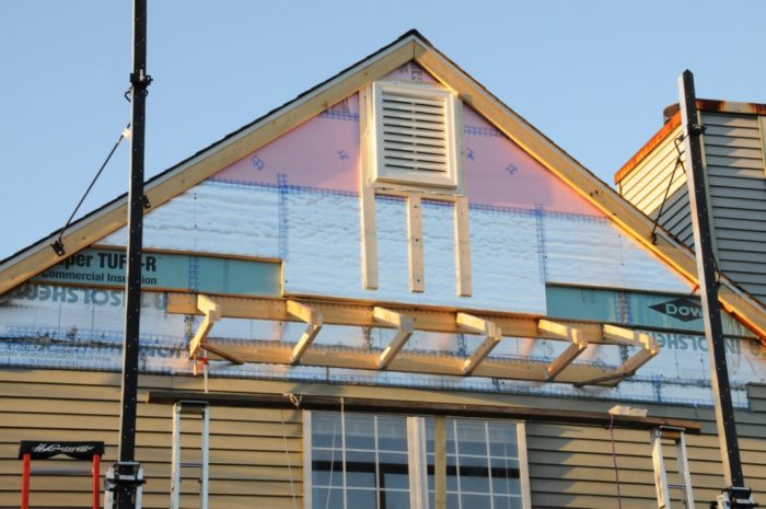
Extending the roof overhangs
How do you add 4 inches of foam board insulation to the exterior of the gable end walls when the original walls are already flush with the edge of the roof? One answer is that you extend the roof a bit. Doing this required unweaving some shingles away from the existing edges so I could weave in new ones all the way to the new, extended edges.
The roofs were extended by first lagging regularly spaced blocking made from 4x4s to the original verge rafters, and then nailing new barge rafters onto the spacers. I also added widths of new roof sheathing. That was a painful process, but was needed for two of the three gable end walls, and it was one of the biggest challenges of the entire project.
Of course, the gable walls at the level of the attic have no need for insulation, but it seemed easiest to just continue the plane of the foam board all the way up to the peak. In the end, this proved a useful base for the addition of solid sheathing, a requirement for the plastic shake siding that was installed at the gable ends.
More shingle weaving was necessary when I removed our old metal fireplace, along with the entire upper part of its chimney.
Foundation and floor insulation
The foundation consists of concrete footers, concrete block frost walls, and poured slabs. Originally the foundation had no insulation. Using a rented excavator, I excavated the entire perimeter of the foundation down to the footers. Two layers of 2-inch XPS (totaling R-20) were added all around the exterior of the frost walls, extending vertically from the top of the footers to the bottom of the 2×4 sole plates. I installed sheet metal flashing, bent by a roofing shop, over the foam for its protection. The metal flashing extends well below grade.
The concrete slab is in two parts, with a split-level effect. The upper part supports the kitchen and living room. This part of the slab is still not insulated; it only has the R-20 perimeter insulation. The kitchen and living room floors had been upgraded with a mix of hardwood and tile just before I was bitten by the energy efficiency bug. There was no way that I was going to take up this brand-new flooring to add floor insulation.
The other part of the slab sits under the family room and utility room, and supports two stories. This larger section of slab was completely covered with a framework of 2×4 sleepers, with the long edge set vertical, and the framework was filled with XPS foam board. The XPS has a nominal R-value of 17.5, before subtracting a derating factor due to the wood framing.
Net zero ready
The building used 6,772 kWh of electricity between May 2014 and May 2015. That demand could be offset by a properly oriented 5.5-kW PV array. In fact, within a few weeks the house will have a new PV system.
Now that my work is almost done, I’m really happy that I took the approach of reducing the energy footprint of the house as much as I could before adding the solar panels. It would have felt completely unnatural to me to employ PV back when my electrical load was a little more than double what it is now. Enough PV to meet the former load would not even have fit on the roofs.
Now the house will be net-zero, with some electricity left over to charge an electric car in the future. To me, the approach hints at, and shows some measure of respect for, the beauty of efficiency found in nature.
Weekly Newsletter
Get building science and energy efficiency advice, plus special offers, in your inbox.
Lessons Learned
• With more experience, I probably would have installed a layer of blown-in cellulose instead of fiberglass batts above the existing attic insulation. The cellulose would pack tighter, lessening the chance for air circulation and associated heat loss.
• Everyone (including me) talks about how nice and efficient minisplits are. However, I haven't heard anyone talk about how extremely difficult it is to to internally clean the heads. After about a year and a half, there was so much dust caked on the cylindrical fan that it bogged down and it had to be cleaned. The entire tightly packed unit has to be totally disassembled while it and its components hang on the wall, without benefit of a workbench, to remove the fan for proper cleaning. It takes several hours of painful work. I would gladly accept a larger head design, perhaps even one that is less attractive, if that design allowed the fan to be readily removed for cleaning.
• I wish I could have found reasonably priced windows with clear glazing — glazing with no low-e films and a higher SHGC — for the south side of the house. As I recall, those simple windows can be found, but at a higher price than windows with low-e films.
General Specs and Team
| Location: | Middle River, MD |
|---|---|
| Bedrooms: | 3 |
| Bathrooms: | 2 |
| Living Space: | 1438 |
Design and construction by the owner
Construction
Foundation: Concrete slab on grade with frost walls on footers.
Foundation insulation: R-20 vertical XPS at exterior of frost walls; horizontal XPS (about R-15) over some of the slabs.
Wall insulation: Two layers of staggered and taped 2-inch polyiso over 1 inch of EPS over 2x4 wall insulated with fiberglass batts; wall assembly totals about R-34.
Attic insulation: Two to three layers of R-19 fiberglass insulation over 12 inches of blown-in fiberglass; total R-value is about R-70.
Windows: Fiberglass-framed Accurate Dorwin windows are a mixture of fixed windows and casements. North-facing windows are triple-glazed and argon-filled (average U-factor = 0.16). South-facing windows are double-glazed and argon-filled (average U-factor = 0.30; average SHGC = 0.57). South windows are shaded by overhangs to limit summer solar heat gain, and include interior ComforTrack thermal shades.
Space heating and cooling: Two ductless minisplit air-source heat pumps (a Fujitsu 12 RLS2 on the first floor and a Fujitsu 9 RLS2 on the second floor)
Domestic hot water: GE Geospring heat-pump water heater
Energy
House designed according to passive solar principles (extra south-facing glazing, minimal glazing on other orientations, extra interior thermal mass, and careful design of roof overhangs on south side).
Blower-door test: 4.09 ach50; 0.23 natural ach (calculated).
Energy Specs
Electricity use before improvements: 14,764 kWh/yr
Electricity use after improvements: 6,772 kWh/yr


22 Comments
GREAT JOB!!!
Just a GREAT GREAT JOB!!
Response to R. Miller
R.,
I'm not sure if you are the author, patting yourself on the back -- or perhaps the author's cousin, expressing familial pride? [P.S. -- I just heard from the author, Rick Miller. He didn't post the comment.]
In any case, I agree -- great job.
Painful cleaning of minisplits
I enjoyed reading your blog Rick. I'm contemplating a switch to minisplit heating and cooling and I thought I knew everything about them, but I've never heard somebody complain that they get dirty inside and must be cleaned through a difficult process. Can you please tell me more about what happened to your unit that alerted you to the problem? Did you do the cleaning yourself? Anyone else ever heard of this problem?
Painful cleaning of minisplits
Patrick,
I would also like to hear if anyone else ever heard of the problem and, even better, some easy way to do the cleaning. I would be happy to hear that I did something wrong, if it would make things easier for the future.
This past summer, the fan bogged down noticeably, and you could look in and see dust caked up a little bit on the vanes. The screens on the unit had been cleaned regularly but, think about it-- these fans run almost all the time during the seasons, the screens are small, a lot of air gets moved, and there is no way those screens are stopping everything. In all fairness, my fan may have gotten clogged up a little faster than normal because I had been doing some inside work in an adjacent room and making a little more dust than normal. That dust coupled with plenty of moist air to be processed around here in the summer may have accelerated the need to clean, but I have to believe all mini-split owners will experience the need for a major cleaning at some time.
I have heard of people aiming an air hose up into the fan from outside the unit to clean it, spinning the fan with dust flying everywhere, but I don't want to do that--it's a good way to jam dust into, and clog, the delicate aluminum cooling fins.. You can reach into the fan vanes from outside with something small and try to painstakingly clean each vane, but I didn't find that to be very thorough
I did the cleaning myself, with disassembly instructions provided by Fujitsu. The instructions include pictures, but they are no where near complete. There are more screws, clips and parts to remove than they tell you about. The electrical section (wiring box) has to be removed--they tell you that but perhaps it is too embarrassing for them to state that in order to do that, the unit has to be unwired from the power wires in the walls. In short, the unit has to be almost totally disassembled, since the fan is totally embedded among other tightly packed components. In the end, the "blower wheel, drain pan, and motor should drop out of the unit." Actually, even at this late stage of disassembly, with many screws and other components removed, those elements have to be forced to "drop out," since they are still held in by closely packed soft and hard foam, used for insulation and vibration damping. Finally, the assembly does come out and hangs by the drain hose up against the wall. This is not good in an environment you are trying to keep clean. You also need 4 hands, or a work bench mounted on the wall directly below the unit, which, of course, is not very practical. .
Efficient Tract House
I love these success stories. In this case quite a bit of rebuild was involved. Very impressive. It shows that an old house can achieve respectable energy efficiency with projects like those mentioned and in the hands of a skilled craftsman. The electricity usage is now only 46% of the historical usage. Smooth. Apparently there is no natural gas in use.
The two smileys were earned for January/February and showed 57% less energy usage compared to neighboring homes of similar size and configuration. Were the warm weather comparisons also 57% lower?
Congratulations and thanks for sharing and carefully documenting the specification particulars.
Reply to wd
wd,
Thanks for the compliments--I really worked hard on everything.
Like you, I also like to see the specification particulars for different homes.
There is no natural gas service-all electric.
The warm-weather neighbor comparisons have been somewhat lower. For example, the house used
43% less electricity than the most efficient neighboring houses in July and August of this year.
.
Bigger Mini-split heads
I second your suggestion of bigger heads on our mini-split heat pump installations. I've not noticed a problem with dust, but I found that in my installation my 18k BTU and my 9k BTU mini split heads are almost the same size. It appears the way that the extra BTU's are achieved in the 18k BTU unit is by pumping far more (higher velocity) air through the unit and that means that, while the 9k BTU head is whisper quiet, the 18k BTU head far louder than I expected. If I had known that, I might have asked for two smaller units instead of the single 18k BTU unit. Your suggestion of having a larger head might have achieved nearly the same results.
Reply to Jason
Thanks for your comments. I think you are saying you have not yet seen enough build up on the fan vanes to warrant disassembling the unit. I hope you don't. Can you tell me how long you have been running it and in what sort of environment? I'm now hoping that maybe my house was a little more dusty than I had thought, when I was doing a bit of construction work inside, and that my problem won't recur for quite some time.
As for head size, I'm sure these mini-split manufacturers are highly sensitive to people who are highly sensitive to aesthetics (and there apparently are many many of those people), and so they try to force components inside the smallest possible package. I really think they went way to far with it, but I didn't see that ahead of time when I chose the mini-splits,
Ventilation upgrade?
Rick,
Great write-up of a successful project!
An item of interest to me is the ventilation strategy for your renovated home. Did you retain the old system or upgrade? How's it working?
Thanks;
Ed
Response to Ed
Thanks for the compliment. The results have been so satisfying that I (almost) want to do it again.
There was no ventilation upgrade; I kept the original ventilation scheme.
Mini split cleaning solution
I have noticed a similar problem with the blower wheel in my minisplit. I have seen a few models that have better designs that allow you to gain access easier.
Compressed air isn't really a solution, unless maybe your bringing a monster psi, it didn't work for me as the gunk is stuck on good (the wheel is spinning and moving air through it yet it doesn't come off with that force) and due to the way the blades are shaped on the scroll wheel, I didn't have any luck with a homemade brush I've rigged up to insert.
I've resorted to laying a piece of carbon filter screen over the minisplit inlet to help keep the build up at bay. You can buy bulk sheets and cut to fit, although the Fujitsu RLS2 series with its motorized face makes a custom fit difficult.
There is a solution though, although it's pricey, especially if you want a powered sprayer instead of using a pump sprayer which may not have enough pressure or require a few applicatoins.
This also cleans the fins as well, which you can also accomplish with a easy to use foam can spray, but it can't reach the scroll wheel blower (it's shielded by the condensate drip tray, however the power sprayer can shoot up through the exhaust, although you may have to shield the upper wall.
http://www.speedclean.com/product/mini-split-bib-kit/
The actual material cost is probably pretty low if you can figure out a way to fabricate the frame; plastic sheeting is cheap
Nice detailed write up Rick.
Minisplit cleaning
Bob,
Thanks for the compliment, and for the cleaning information. That approach looks potentially messy
and maybe not effective, but I just might try it. It is a total disaster to totally disassemble the unit for
cleaning, the way I did. In addition, the front cover and other parts are so flimsy, several things could break without extreme care during disassembly, particularly the flimsy plastic inner cover.
google minisplit bib kit for
google minisplit bib kit for some youtube videos of examples and similar products. as long as you have plastic sheeting tucked/taped all around, and the shroud on bottom and probably another on top, it shouldn't be too messy, just takes some prep which beats deconstructing the whole unit. You also need the water to transport the dust you remove else it is gonna be airborne.
The RLS2 was def not designed to be disassembled to be cleaned, and there doesn't seem to be any other way to effectively remove the gunk than to use pressured water.
In one of my prior attempts I tried all sorts of brushes and hacks, I even cut out the wire guard on the exhaust, but there is just no easy way to get in between all those tiny fins; like trying to clean a giant cylindrical sets of mini blinds stashed up in a chimney vent.
It probably varies by unit and by the temp swing - I see more dramatic ones when it is really cold - but all that plastic really creaks and groans, so dissembly would probably make it worse.
A hand pump sprayer will probably hold enough pressure to work, I have yet to try it; gonna do it once winter is over.
Middle River, MD
Rick, This is a great article. My wife and I are planning to build a house in Delaware that will be similar in size to yours. You have provided a great deal of useful information. We are interested in the name of the supplier you bought the Fiberglass-framed Accurate Dorwin windows from.
Delaware House and AD Windows
Virgil,
Thanks for the compliment--feels good.
If you are interested in energy efficiency and maximizing help from the sun (really, nature's way), then you can easily do better than I did. I had to work with a retrofit--my first choice would have been to build from scratch.
The main ways you can do better are:
--Simple, relatively rectangular design with a long side facing solar south.
--Better air sealing and a lower ACH 50-- but remember you have to add deliberate mechanical ventilation in the form of an ERV or HRV (or other methods), if you achieve better air tightness than I did. (See ASHRAE or your local building code for ventilation requirements).
--Better approach to attic insulation, including, perhaps, energy trusses for increased insulation
thickness near the eaves.
Read as much as you can. It's not that hard in this information age to know as much or more
about "green" building than many building contractors.
Oh, the AD windows. AD is a relatively small company, with good product, and good customer service (my experience). I believe they still do not use distributors or suppliers, but rather you order direct from them, as I did.
I hope you end up with a great house, and maybe you could post about it at some point.
Answers to Joe's Questions
Two smiley face letters: Nice to hear about other people getting them. The utility stopped sending them to me. I've had PV arrays since the end of last December. For March, the PV produced more than I could use, and it put about $26 worth of electricity back on the grid (meter ran backwards).
I don't remember much about my original heat pump. It was replaced by another 3-ton Trane unit (the one in the pictures) in 1998. I remember that it had about the best specs for that time--something like 14 SEER/8.5 HSPF.
Last winter, I checked the output temperature of my 12RLS2 in response to some question here on the GBA website. I'm not sure I remember, but I believe it was something like 96-98F when it was maybe 32F outside.
I never considered leaving the old air handler (and ducts) in place for air distribution, for the following reasons:
--because of the super-insulation and much less infiltration, I actually have more- even temperature distribution now, with point-source heating/cooling, than I had with the air handler and dedicated ducting for each room. My research on Passive Houses told me, before I started, that this would happen. It's one thing to read that, but pretty amazing to actually experience it.
--ducts/air handler are dusty and less efficient--if you don't need them, don't use them
--the house is small. Many times, I have found myself designing to use every inch of inside space. Creating space by taking out the air handler was like finding a gold mine, and I described my use of this freed-up space in the article.
Thanks
Efficient use of space is a great thing, so I very much understand getting rid of the air handler and ducts for this reason alone, especially if it never worked well to begin with. Our duct system seems to work pretty well, but it helps that it's short and simple and between the two floors (ceiling of lower level- chase) with the air handler in the center of home- lower level.
If it's not too personal, do you have any numbers on the kWhs used for heating and cooling alone (yearly basis) before and after the project? I keep a spreadsheet of all electricity use over time by category. Knowing the HVAC kWhs gives a better idea of the impact of your project because the other electricity use can vary from household to household.
Great that you have gone net zero with solar! Save some of those credits for the future plug-in vehicle. FWIW, our electric use went up app. 22% (1,882 kWh, 8,100 miles, city driving) over the last year with our Nissan Leaf. Of course, the more efficient the home is the larger the % increase with electric driving. I usually explain it, to those interested, in energy cost/mile when comparing ICE to BEV. It then becomes easy to scale it up to 1K miles and budgeted "fuel" expense per month that anyone can understand. Since most people don't yet own a BEV or PHEV, I always subtract this electricity use from the totals when comparing home use to make it apples to apples.
Great Work!
I really enjoyed reading this blog. There are similarities to us with the same era home and the same utility efficiency rating system (Opower). We also get the two smiley faces, but it's disappointing for society's sake that we use 34% less electricity than the efficient neighbors and 60% less than 100 comparable neighbors. Either it's lots of ignorance or electricity is still too cheap at $.152/kWh retail before tax.
I have a few questions. Did the original heat pump actually last 32 years and do you know the app. SEER/HSPF rating? What air temperature does the mini-split produce at grill at 32F, 0F? Did you ever consider leaving the old air handler with filter in place to distribute the cool air from the lower level mini-split to the upstairs level through the air handler/ducts (assumes a low speed "always on" fan setting- 400 CFM, 30 watts with our 2.5 ton HP) and also to provide emergency backup strip heat if a mini-split fails in winter?
Our house, built in 1982, is also fully electric. It came with an inexpensive electric furnace that blew loud and fast. We replaced that in '01 with a 13 SEER/8.5 HSPF single stage air source heat pump. One of the reasons we went with the unit was the advertised register temps of 98F-100F, and it does produce this most of the winter in S. IN. At the coldest outdoor temps.(0F to -10F), the register in our bedroom drops down to 80F-85F. Because the unit also blows air slowly (user selectable- comfort/slow versus eco/fast mode) and has a slow air ramp up when the compressor starts, it's not really noticeable at the registers. Only during defrost mode (1-3 minutes) does it blow enough air volume to be noticeable.
I'm frugal and the HP is set for the electric strips to only come on below 5F for auxiliary and never during defrost mode. In testing, it only seems to come on between 0F and -5F (thermal balance point), so our load is pretty low (8K-10K BTUs/hr. ave. in January) for 2160 sf bi-level with R60+ attic, R10 walls with full brick siding that has condensation/air gap, and partially insulated, fully conditioned lower level. Air handler and all ductwork are inside conditioned space.
I'm thinking about mini-splits, but also waiting on new V2 high efficiency (HSPF 13+) split HPs that should come out this year. As I don't want the R-22 venting to the atmosphere in a system failure, I will probably replace the current unit in the next few years.
Exit air temperatures of mini-splits (response to Joe Dwyer)
The exit air temperature of a mini-split varies with both outdoor temp and modulation levels, but are generally in the ~110F range across a wide range of mid-load levels, including both minimum & maximum modulation @ +32F outdoors for most vendors.
For exit air temps of the Fujitsu 12RLS2 at different outdoor temperatures & modulation levels, see Table 5, p.26 (p.34 in PDF pagination) on this bench test data set:
http://www.nrel.gov/docs/fy11osti/52175.pdf
Looks like ~94-117F when it's in the 30s outside, 94F at min-modulation, 117F at max. Unlike the Table-6 data for the Mitsubishi FE12NA they didn't specify the exact outdoor temperatures, but it's the H-SS-35-H-MX (max output), H-SS-35-M-INT (intermediate), and H-SS-35-L-MN (minimum modulation) lines. Curiously, the measured minimum modulated output in this 3rd party test data set is higher than specified in the energy performance rating submittal data sheets under HSPF test conditions:
http://www.fujitsugeneral.com/PDF_06/Submittals/12RLS2%20Submittal.pdf
Assuming that it puts out mid-90s and delivering ~6500 BTU/hr at min-mod when it's in the 30s as tested by the Ecotope engineers, if Rick Miller was measuring 96-98F the heat load had to have been in the the ~6500-7000 BTU/hr modulation range, which is about right for a ~1500' house at those insulation levels. During sunny days that can happen even at temps much lower than 32F due to solar gains covering all or most of the load, but it modulate up to a higher output and higher exit air temp at night as the load increased.
Dana Dorsett- Thanks.
Just the data I needed. Pardon me Rick if I ask Dana a question. I don't mean to steal the thread.
Mini-Splits seem to provide good to great exit temps. Interestingly, the study said the 12RLS2 couldn't provide cooling capacity below 5K BTUs/hr. without shutting off. That's only 42% of capacity. Therein lies the issue at hand with multi-story dwellings and air stratification. I'm looking for near constant temps. ceiling to floor and level to level. Carrier solved this issue with the low speed fan option, but it can't be used during the cooling season because it evaporates the water on the indoor coil and unacceptably raises indoor humidity levels. It works great during the heating season, as designed. The solution seems to be variable capacity and modulation (always running) and not using the low speed fan setting for distribution. But with a tight and energy efficient home, this means that very low levels of modulation are required to meet low demand and also prevent air stratification. One could theoretically use an air handler with properly sized ducts for distribution and air cleaning and one or more mini-splits for heating and cooling/dehumidification in combination. Has this topic been discussed before? It seems like it's almost universal in application to multi-story homes.
Mind you, those designs are a decade old.
The RLS2 and the Mitsubishi FE series are getting to be a bit long in the tooth. The RLS3s have been out for something like 2-3 years now(?), as have the Mitsubish FH units. The newer series come with higher SEER/HSPF numbers, and sometimes bigger modulation ranges.
The 3/4 ton FH09NA and half-ton FH06NA can both (according to the submittals) dial back to 1700 BTU/hr in cooling mod, 1600 BTU/hr in heating mode, yet can still deliver 12,000 BTU/hr @ 90F and 10,900 BTU/hr @ +5F in heating mode. That's about half the (published) min-mod output of the 9RLS2 or 12RLS2. Due to the very low minimum modulated output its possible to heat and cool a number of 2000' two story houses efficiently with a pair of them, one per floor.
The efficiency of using ducted systems for reducing stratification is pretty low, since at low delta-Ts it takes high cfm.
Is there a cost and material
Is there a cost and material breakdown that you could post? Considering almost the same project for my house, minus the heating/cooling system changes.
Log in or create an account to post a comment.
Sign up Log in