
Image Credit: All illustrations: Andrea Love
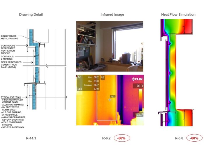
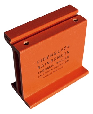
Image Credit: All illustrations: Andrea Love An example from a rainscreen study showing the intended detail and R-value, as well as the R-value observed from a thermal image and through the heat-flow simulation. This fiberglass rainscreen thermal spacer made by Cascadia Windows is an example of a thermally broken rainscreen support.
More Guest Blogs


Over the past 20 years, the building industry has experienced renewed interest in reducing the energy demand of buildings. At the building code level, groups such as the American Society of Heating, Refrigerating and Air-Conditioning Engineers (ASHRAE) have been steadily raising the bar on performance criteria for building envelopes and systems. Designers have been challenged to find and implement technologies and solutions that can practically and economically affect the energy demands of our buildings.
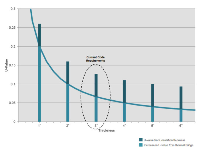
Less progress has been made, however, in managing conductive losses through improved building insulation performance. Increased thickness of insulation materials provides diminishing returns if thermal bridging is not considered, as seen in the illustration at the top of this article.
The intent of this research is to quantify and understand how built façades perform, and also to investigate proposed improvements to common problem details. Results show that it is possible to reduce thermal bridging by 50% or greater by employing careful detailing and products that are readily available.
A research project looks at the impact of thermal bridging
The research project was comprised of a multi-step approach, starting with field observations of existing assemblies, followed by computer simulations of existing details and proposed thermal improvements. Hand calculations of R-values based on the resistance of each layer of the envelope were derived from shop drawings, construction documents, and/or specification information as appropriate. Because these simplified, single-dimension calculations do not account for any thermal bridging, they were used as the “baseline R-value” as the best-case scenario.
A thermal imaging camera was used to determine the actual R-value of existing façades. Teams were deployed to 15 buildings to assess the general envelope thermal performance and scan for areas that appeared to perform differently. Using the methodology published by Madding (2008), the exterior air temperature, interior air temperature, and the radiant temperature were gathered using infrared imaging and temperature data loggers in order to calculate the as-built R-value of the assembly.
Because physically altering the built conditions was not possible, computer simulations were used to test possible improvements to various construction details. Lawrence Berkeley National Laboratory’s THERM 7.3 program was employed to determine R-values of complete assemblies, including thermal bridges, based upon its ease of use and ability to integrate into the design process.
For each detail, models were prepared of the constructed designs, and were then calibrated by comparing them to the actual performance measured in the field with the thermal imaging camera. For discontinuous thermal bridges, such as bolts or clips, two methods were used to account for their three-dimensional impact: the parallel path method and the isothermal planes method. The parallel path method takes a weighted average of two simulations, one with the discontinuous bridging element and one without it. The isothermal planes method runs one simulation using a weighted conductivity of the bridging material and insulation for the discontinuous thermal element. Because the parallel path tends to overestimate the impact of the thermal bridging, and the isothermal planes tends to underestimate the impact, both methods were used to understand the range of impact the thermal bridge might have.
Working from both the graphical and quantitative output from THERM, models were strategically probed to identify the significant heat transfer elements within a given detail, and ultimately predict the performance improvements that might result from changes in detailing.
Case study on rainscreens
The investigation fell into two categories: façade systems and assembly transitions. The most thermally problematic transition conditions were found at window installations, foundation-to-wall transitions, changes in wall systems, soffits, roof-to-wall transitions, parapets, roof penetrations, louver openings, existing buildings with embedded beams, and slabs and seismic and movement joints.
Five basic façade systems were identified that would be generally applicable to modern commercial and institutional work and appeared to reflect different challenges. These were: rainscreens, masonry veneer walls, insulated metal panels, curtain walls, and the renovation of existing masonry façades. Rainscreens are discussed in further detail below.
Rainscreen clips and rails are thermally conductive
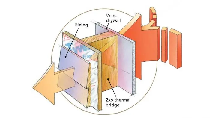
Rainscreens are popular for commercial façades due to their ability to control air and moisture movement. Because the cladding is held off the wall, these systems require a secondary structural system of rails, Z-girts, and/or clips to support the cladding. Typically made of highly conductive metals, these members penetrate through the insulation, causing significant thermal bridges. While insulation between steel studs has long been acknowledged to cause thermal bridging, these rainscreen supports have a similar impact thermally that was overlooked until recently.
In thermal images of rainscreen façades, a decrease in thermal performance that ranged from 20% to 60% less than the design intended performance was observed, with the majority around a 45% to 55% decrease. The systems selected for study all had between 2 in. and 3 in. of insulation with various support systems such as vertical and horizontal Z-girts, as well as different clip systems.
In both vertical and horizontal orientations, Z-girts demonstrated roughly a 45% to 55% reduction in performance depending on the insulation thickness. Because of the intermittent nature of the rainscreen clips, they performed better both in thermal images and in the computer modeling than the continuous Z-girts. The clip support system had half of the heat flow of the Z-girts, or 25% of the design intent. While the intermittent nature of the support system certainly improved the performance, the team investigated methods to further improve the performance of rainscreen support systems.
A number of thermally broken Z-girt and rainscreen support systems currently exist on the market. As part of the research project, the team explored four thermally broken options. All four of the tested systems performed well. In general, the R-value of the assemblies was only reduced by 10% to 15% due to thermal bridging through their support systems.
Try to eliminate continuous conductive elements that penetrate the insulation
The continuity of a thermal barrier across the entire building envelope is fundamental to good thermal performance. It reduces energy consumption, increases thermal comfort, and helps to prevent condensation. While some thermal bridges may be eliminated, the real goal of the research suggests that thermal bridges can be effectively managed, and that doing so will have a meaningful impact on the performance of buildings.
The first priority should be to eliminate continuous conductive elements, such as Z-girts or masonry shelf angles that completely penetrate the insulation layer. These systems are easily interrupted by pulling them outboard of the thermal barrier and using discontinuous supports to make required connections back to structure.
Second, try to utilize available thermally broken products or strategies to disconnect the heat flow through the thermal barrier. Thermally broken rainscreen support systems, brick ties, and concrete slab connections are readily available on the market. It is essential, however, to ensure that the thermal break occurs within the insulation boundary in the application of these products. The research found some products that are easily foiled by having breaks in undesirable locations relative to the natural placement of insulation.
Finally, when the thermal bridge is a necessity, such as when structure must penetrate uninterrupted through the insulation, look for materials with the lowest possible thermal conductivity. For example, stainless steel has one-third the conductivity of carbon steel, and fiberglass’s conductivity is significantly lower than that of stainless steel.
While this study is not intended to be an exhaustive analysis of all thermal bridges, it does identify the types of conditions that occur typically, and helps quantify their localized impact. More than anything, it is anticipated that this research will help to develop an intuitive understanding of the situations that lead to the thermal bridging regardless of the specific project conditions, and provide the tools for easily addressing them.
Andrea Love is the director of building science at Payette, a Boston-based architectural firm, where she leads the firm’s sustainability and research efforts. This article, which was originally published in the fall issue of BuildingEnergy, was peer-reviewed by Hannah Durschlag.
Weekly Newsletter
Get building science and energy efficiency advice, plus special offers, in your inbox.


0 Comments
Log in or create an account to post a comment.
Sign up Log in